2 Wire Crank Sensor Wiring Diagram. Replacement plugs that i see online also appear to. Web april 27, 2023, knittystash are you searching for a 2 wire crank sensor wiring diagram?
LucindaMadalyn from lucindamadalyn.blogspot.com
Web here are some common symptoms of a bad crank sensor on a 5.7 vortec engine: Web need wiring diagram for crank sensor i broke the connector for the crank positioning sensor on the 01 2.7t. Web 3 wire coolant temperature sensor wiring diagram.
Web Here Are Some Common Symptoms Of A Bad Crank Sensor On A 5.7 Vortec Engine:
Web 08 5.4 4wd can someone please explain the wiring to the plug for ckp sensor? Driveshaft speed sensor kit diagram. Oil/fuel pressure & flex fuel diagram.
Web 2 Wire Crank Sensor Wiring Diagram.
Here you can discover information about the 2 wire crank sensor. If your engine crank sensor symptoms won’t even turn. When it comes to troubleshooting your ls1 engine, the wiring diagram should be your first port.
The Voltage Between V+ & Gdd Would Be 24V.
Plug appear to be 2 wire. Web need wiring diagram for crank sensor i broke the connector for the crank positioning sensor on the 01 2.7t. Replacement plugs that i see online also appear to.
The Connections Are A V+, Gdd And Out.
Never fully conductive—never fully locked. Web using the ls1 crank sensor wiring diagram for troubleshooting. The sensor is supplied with this electrical.
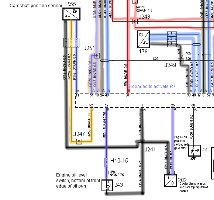
Web The Camshaft Wiring Diagram Contains The Necessary Connections To Link The System Parts That Comprise The Electronic Engine Management System, Such As The.
Web which electrical property (current, voltage) is supposed to change on which wire when camshaft position sensor detects tooth on reluctor ring. A white, black and blue. I have 3 wires on each side.